Tool-Free Terminal Selection for Industrial Equipment (2026): Five Scenarios and the Ratings to Check
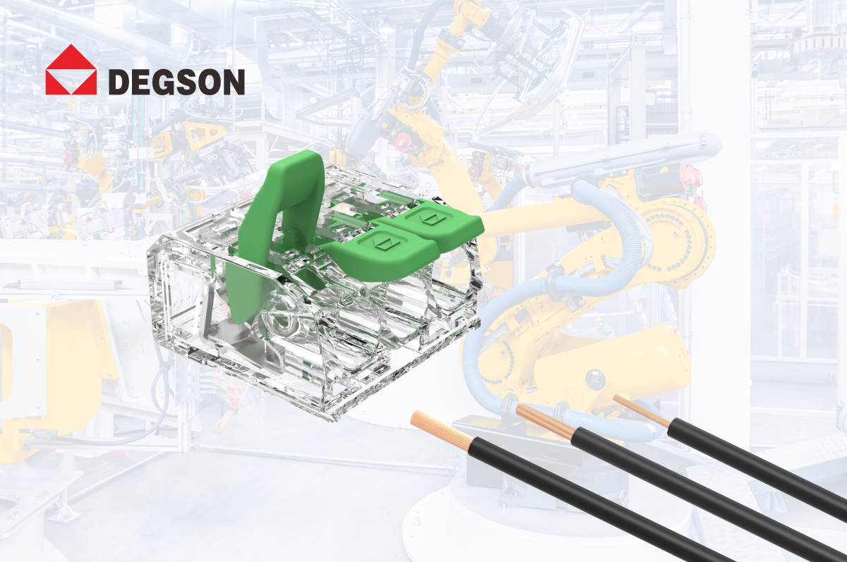
Tool-free spring terminals are worth evaluating when equipment shows any of four characteristics: wiring labour is a significant share of line time and the assembly cycle needs shortening; components such as cooling fans, door switches or fuses are replaced periodically and downtime must stay short; the junction box is too tight for a screwdriver to reach a screw terminal perpendicular to the board; or field staff have varying skill levels and wiring error rates need to come down. If none of these apply, a screw terminal remains a valid choice — the case for switching is operational, not electrical.
This article covers internal power and signal terminals in industrial automation equipment, control cabinets, robots, semiconductor equipment and AGVs. It does not cover distribution above 450 V, power circuits above 32 A, or directly exposed outdoor environments — those need terminals rated for the corresponding class, and the ingress protection has to come from the enclosure rather than the terminal.
Four criteria decide whether a tool-free terminal fits before any part number
Screw terminals, crimp caps and taped joints all remain in service, and each fails in a specific way under one of the conditions below. Working through these four in order is faster than comparing datasheets.
Tool dependency and cycle time.
A screw terminal requires a torque-controlled driver, and where assembly is audited, a torque record per joint. A push-in spring removes both for solid and ferruled conductors. Crimp caps remove the driver but shift the variability into crimp quality, which depends on operator technique and is difficult to verify after the fact — which is precisely why they appear in the rework statistics of high-mix lines.
Repeatability across operators.
Spring clamping applies contact force from the spring itself, so it does not vary with how hard an individual tightened the screw. This is the property that matters when maintenance is performed by field staff rather than the original assembler.
Serviceability without re-stripping.
Taped joints and crimp caps have to be cut and re-stripped when a component is replaced. A lever-actuated terminal releases the conductor mechanically, so a fan or door switch swap becomes: lift lever, remove wire, fit new component, insert wire, close lever — with the original strip length reused.
Measurement without disconnection.
If the terminal is a commissioning test point, an integrated test hole is a requirement rather than a convenience. Without one, checking continuity or voltage means loosening a live conductor.
Where these criteria point to a spring terminal, the DEGSON DGBSC-SG series is one candidate that meets them structurally: PUSH-IN spring clamping with a rotatable operating lever, a transparent housing that makes conductor insertion and strip length visually verifiable, and test holes for probing without removing the wire (DGBSC-SG01/4 product page). Its ratings and boundaries are set out in the parameter section below.
Five industrial scenarios and how the parameters match
The scenarios below are grouped by what actually constrains the selection — consistency, replacement time, space, contamination, or pole count — rather than by industry.
Cabinet air conditioners: replacing crimp caps for wiring consistency
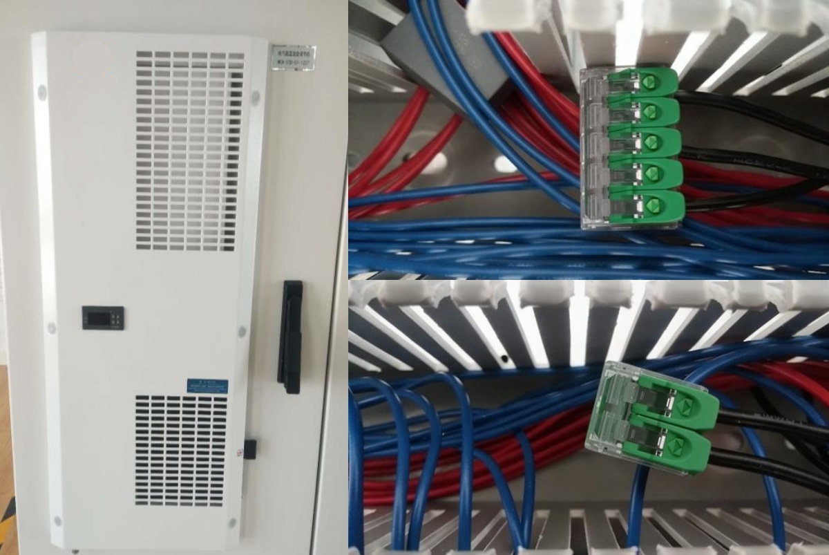
Temperature and humidity controllers in electrical cabinets are commonly wired with crimp caps. Crimp quality then depends on operator feel, the wiring is difficult to trace, and testing or modification requires undoing the joint. The DGBSC-SG01/4 addresses the specific failure mode here — inconsistency between operators — because clamping force comes from the spring rather than the crimp, and the transparent housing lets the wiring state be inspected without disassembly.
Parameter matching: fan, compressor control and power circuits in these units typically draw 10–20 A, against the SG01/4's IEC rating of 32 A at 450 V (overvoltage category III, pollution degree 2), which leaves working margin. The 2P and 3P configurations cover single-phase power and signal circuits.
Boiler-room cabinets: cutting replacement time on wear parts
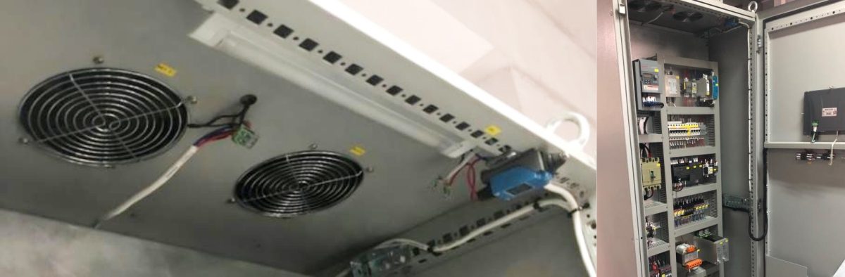
In fire-tube and waste-heat boiler cabinets, cooling fans and door switches are wear parts on a replacement schedule. Where these are wired with taped joints, each replacement means cutting, re-stripping and re-taping — time-consuming, and the joint quality varies each time. The lever on the DGBSC-SG01/4-02P removes both the tool and the re-stripping step.
Parameter matching: boiler rooms combine elevated ambient temperature with continuous low-level vibration. The SG01/4 is specified for −40 °C to +85 °C, subject to the derating curve on the datasheet — that qualifier matters here, because the 32 A figure applies at reference conditions, not at the top of the temperature range. On the vibration side, spring clamping maintains contact force independently of retained torque, which is the mechanism by which screw joints loosen; the series datasheet does not publish an IEC 60068-2-6 vibration grade, so where a grade is contractually required it should be requested from DEGSON directly rather than inferred from the clamping principle.
Robot positioner junction boxes: fitting the wiring into the available volume

Positioner motor junction boxes on welding robots combine limited volume with a high conductor count, and bulky screw terminals interfere with each other during wiring. The 4 mm² DGBSC-SG series body height of approximately 10.2 mm reduces the volume required compared with a comparable screw terminal, and the 32 A / 450 V rating covers motor power and signal connections.
Parameter matching: positioner motors draw high inrush current, so selection should allow 1.5–2× margin over continuous current — a rule of thumb, not a rating, and the actual inrush should be measured on the specific motor. Multiple 02P units mounted side by side fit more circuits into the available width. Note that the lever needs swept volume to open: confirm the open-lever envelope against the drawing, not the closed-state footprint, since a tight box can accommodate the terminal but not the hand movement to operate it.
Semiconductor measurement equipment: moving off direct soldering
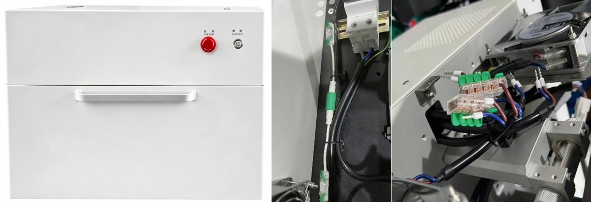
In a desktop wafer measurement laser system, the original wiring was directly soldered, which made maintenance and upgrades awkward: every service action required a soldering iron inside a clean environment. Replacing this with DGBSC-SG01/4-05P for power distribution and DGBSC-SG02/4-01P for fuse connections makes the connection serviceable without solder fumes or stripping debris in the enclosure.
Parameter matching: the 05P configuration consolidates multi-circuit distribution into one terminal, reducing both terminal count and mounting area. Where a cleanliness class is specified for the equipment, confirm that the terminal materials are acceptable — the housing is polycarbonate and the contacts are tin-plated copper, per the datasheet.
AGVs: pole count and serviceability in a moving platform
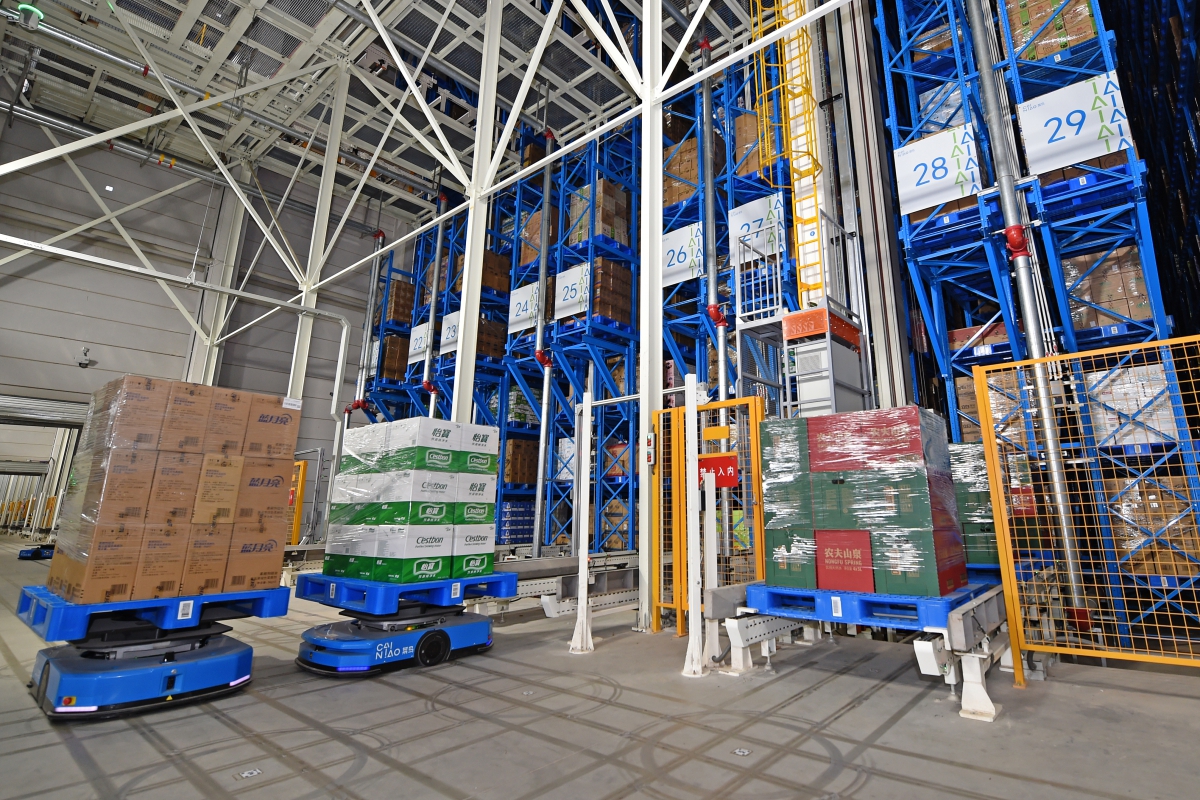
AGV internal wiring has to satisfy reliability, serviceability and compactness at once. The DGBSC-SG01/4 is available in 02P, 03P and 05P, covering battery circuits, drive motor signals and sensor wiring. Tool-free termination saves assembly labour on the line, and field staff can isolate a circuit and replace a component without carrying a driver.
Parameter matching: AGV battery circuits see wide current swings, so size on continuous discharge current with margin rather than on average draw. With vehicle space constrained, the 05P reduces the number of side-by-side terminals, which helps both layout and the total width consumed by lever clearance.
Ratings and certification scope of the DGBSC-SG series
Two rating systems apply to this product, and they produce different numbers for the same part — comparing across them is the most common specification error in this category.
| Parameter | Specification |
| Connection method | PUSH-IN spring with rotatable operating lever |
| Conductor cross-section, solid | 0.2–4 mm² |
| Conductor cross-section, flexible | 0.2–4.0 mm² (ferrule recommended) |
| AWG range | 24–12 AWG |
| Strip length | 12 mm |
| Rated current / voltage, IEC (III/2) | 32 A / 450 V |
| Rated current / voltage, UL (use group B) | 20 A / 600 V |
| Pitch | 5.6 mm |
| Body height, 4 mm² series | approx. 10.2 mm |
| Pole configurations | 2P / 3P / 5P |
| Housing material | Polycarbonate, transparent |
| Flammability rating | UL94 V-2 |
| Contact material | Copper, tin-plated |
| Ambient temperature | −40 °C to +85 °C (per derating curve) |
| Test specification | UL 1059 / IEC 60998 |
| Certification | UL (UL-US-2411668-0), VDE (40049336) |
| Environmental | Compliant with REACH / RoHS |
Source: DGBSC-SG01/4 datasheet, order number 10050000465.
Three points in that table are worth reading carefully. First, the IEC current of 32 A and the UL current of 20 A describe the same product under two different test regimes — a specification that quotes "32 A" into a UL-governed market is quoting the wrong number. Second, the housing is UL94 V-2, not V-0; this is a consequence of using transparent polycarbonate for visual inspection, and where the equipment's own fire-enclosure requirements demand V-0, a different series with a PA66 housing is the correct choice. Third, the applicable test specification is UL 1059 and IEC 60998 — not IEC 60947-7-1, which governs DIN-rail terminal blocks and is frequently mis-cited for PCB terminals.
On certification: the DGBSC-SG series holds VDE certificate 40049336 and UL certificate UL-US-2411668-0, both of which can be checked against the issuing bodies' own records — the VDE certificate database and UL Product iQ. Read the scope on the certificate itself rather than the series name: certification attaches to specific models, materials and configurations, and sub-models with different pole counts or conductor ranges may differ in coverage. Where UKCA, CE or an EPD is required for a target market, request the current certificate from DEGSON rather than assuming series-wide coverage.
Four steps to specify, and where the series does not apply
Confirm electrical parameters.
Calculate continuous current and working voltage, and check against the correct rating system for the target market — 32 A / 450 V under IEC III/2, or 20 A / 600 V under UL use group B. Circuits with high inrush or surge should be verified with 1.5–2× margin against measured values.
Confirm the space envelope.
Measure available height and width in the box. The 4 mm² series is approximately 10.2 mm high, and lever operating clearance must be reserved when units are mounted side by side — this is the dimension most often missed, because it does not appear in the closed-state footprint.
Confirm pole count and conductor range.
Select 2P / 3P / 5P by circuit count, and verify the actual conductor is within 0.2–4 mm². Fit ferrules on fine-stranded conductors, and hold the strip length at 12 mm: over-stripping leaves bare copper outside the clamp, under-stripping never reaches the contact.
Confirm certification and environment.
Verify the certificate covering the exact part number for the target market. High temperature, high humidity or corrosive atmospheres require separate material confirmation, and the derating curve — not the headline current — governs at elevated ambient.
Where the series does not apply:
Circuits above 32 A or 450 V, directly exposed outdoor installations, and environments with strong chemical corrosion. In those cases select a higher-rated terminal, a high-voltage terminal, or a connector with its own ingress protection — and note that ingress protection for a PCB terminal comes from the equipment enclosure, not from the terminal itself.
FAQ
Q1: How does the long-term contact reliability of a spring terminal compare with a screw terminal?
The mechanism differs in a way that matters over time. In a spring terminal, contact force is maintained by the spring and does not depend on the torque applied during assembly, so it is not affected by operator variation or by the gradual relaxation that loosens screw joints under thermal cycling and vibration. That is a structural argument, not a measured one: comparative contact-resistance data over life should come from the manufacturer's test reports for the specific part number, tested to the applicable clauses of UL 1059 and IEC 60998. In service, periodic infrared temperature sampling on high-current circuits remains the practical check for either type.
Q2: Can the DGBSC-SG series directly replace screw terminals on an existing PCB?
It depends on three things: pitch, mounting method and pin layout. The SG01/4 has a 5.6 mm pitch and a defined pin arrangement; if these match the existing part, direct substitution is possible. If they do not, the PCB pad or mounting-hole design has to change. Request the dimension drawing and recommended pad layout for the target part number from DEGSON and compare against the existing artwork before committing. For equipment already in production, run a small-batch trial assembly with temperature-rise verification before converting the full build — the lever clearance in the assembled enclosure is the constraint most likely to surface at that stage.
References
-
DGBSC-SG01/4-02P product page and technical data, order number 10050000465. DEGSON
-
DGBSC-SG01/4 datasheet (PDF). DEGSON
-
UL 1059 — Standard for Terminal Blocks. UL Solutions
-
IEC 60998 series — Connecting devices for low-voltage circuits for household and similar purposes. IEC Webstore
-
VDE certificate 40049336, DGBSC-SG series. VDE certificate database
-
UL certificate UL-US-2411668-0, DGBSC-SG series. UL Product iQ
Take the Next Step
Start from the four criteria rather than the part number: if tool time, operator repeatability, service access or in-circuit measurement is what constrains your build, a lever-actuated spring terminal is worth evaluating. To take it further, browse the DGBSC-SG series on degson.com, download the datasheet and dimension drawing for the pole count you need, and request the UL and VDE certificates covering that specific part number — or contact DEGSON application engineering for a sample to trial-fit against your existing enclosure clearance.


