Servo System Connection Selection Guide: Matching Power, Signal, Data, and Motor-End Interfaces (2026)
Servo connector selection should be split into four interface classes—power transmission, signal transmission, data communication, and motor-end connections—because each is limited by a different parameter. Power is limited by rated current, conductor cross-section, and temperature rise; signal by shield termination and contact resistance; data by protocol and pin assignment; motor-end by ingress protection and vibration behaviour. Choosing one connector family for all four is the most common source of field failures.
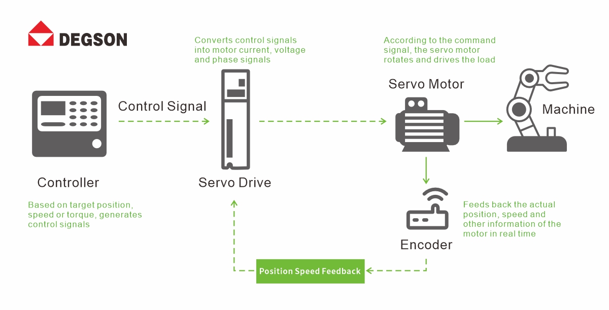
Servo closed-loop architecture showing controller, drive, motor, encoder feedback, and the four connection paths
Closed-Loop Feedback Makes Connections a Reliability Bottleneck
What separates a servo system from an ordinary drive is closed-loop control. The controller issues a command, the drive amplifies it, the motor executes, and the encoder returns position and speed data so the loop can correct deviation. Every element in that loop reaches the next one through a connector, which is why connection quality shows up as control-quality symptoms rather than as obvious electrical faults.
Three failure paths recur in servo commissioning. The first is feedback distortion: encoder outputs are low-voltage differential signals, so rising contact resistance or an incomplete shield termination can let interference reduce positioning accuracy or introduce trajectory deviation. The second is power-path degradation: poor contact raises voltage drop, which under high load can present as a drive undervoltage fault or loss of synchronisation. The third is EMI-induced malfunction: with drives, frequency converters, and welding equipment in the same cabinet, an improperly bonded shield can produce spurious drive alarms.
These are possible failure paths, not inevitable outcomes—whether they appear depends on cable construction, shield bonding, grounding topology, and the drive's own immunity rating. Vibration, temperature cycling, dust, and cutting fluid also accelerate contact ageing, and the resulting intermittent faults are typically the hardest to diagnose because they do not reproduce on a static bench.
Four Interface Classes Set Four Different Selection Criteria
Power transmission
is governed by current-carrying capacity together with the conductor it terminates. Read rated current from the data sheet against the specific conductor cross-section, ambient temperature, and derating curve of the exact part number—not from pitch. A wider pitch generally accompanies a larger contact and conductor range, but pitch is not itself a current rating, and a part selected on pitch alone can be a full rating class away from what the application needs. Note also that IEC and UL figures are separate systems and are not interchangeable: the same part can carry different values under each, and UL further splits by use group.
Signal transmission
balances density against noise immunity. Double-row compact bodies and push-in termination save panel space and wiring time, while side-latching resists vibration loosening. For encoder-class signals, shield coverage matters less than shield termination: a 360° shell is only effective when the cable screen is bonded circumferentially at both the connector and the drive, per the drive manufacturer's instruction. A 360° construction paired with a pigtail bond does not deliver 360° performance.
Data communication
is governed by protocol conformance rather than by connector mechanics. Industrial Ethernet variants such as EtherCAT and PROFINET commonly use RJ45, but the connector form being common does not by itself establish interoperability—pin assignment, shielding practice, cable category, and mechanical envelope still have to be checked against both devices. USB suits laboratory and test-bench data exchange rather than permanent in-cabinet links.
Motor-end connections
face the widest combination of stresses: ingress, vibration, and motor-generated EMI at once. Ingress protection follows IEC 60529, and an IP rating is only valid for the specified mated condition with the intended seals, cable, and correct assembly torque—an IP67 part wired with the wrong gland or left unmated is not an IP67 joint. Vibration performance should likewise be cited against a test level under IEC 60068-2-6, not asserted qualitatively.
Industry Conditions Shift Which Criteria Dominate
Industrial robots.
Joint space is constrained and vibration is continuous. Distal axes favour compact sealed connectors; proximal high-power joints need larger conductor ranges and a locking form that survives repeated articulation. Verify the cable's bend radius and flex-life rating alongside the connector—in a robot dress pack the cable usually fails first.
CNC machine tools.
The dominant stresses are spindle current and the cutting-fluid environment. Temperature rise at the terminal, not just nominal rating, sets the practical limit; and the seal must be checked against the specific coolant chemistry and cleaning regime, since some fluids attack elastomers that pass a plain-water ingress test.
3C electronics manufacturing.
Micron-level positioning makes encoder signal integrity the binding constraint, while compact bodies and push-in termination address the density requirement.
New energy equipment.
Continuous operation and a dense converter population make shield bonding and grounding topology the deciding factors. Sealing requirements vary by placement—an enclosed cabinet interior and an exposed machine frame do not warrant the same IP class, and specifying IP67 everywhere adds cost without adding reliability.
Medical equipment.
Standardised interfaces such as D-SUB support serviceability and integrated wiring, but the applicable device standard and its risk-management documentation govern the final selection.
Applicability Boundaries a Connector Specification Cannot Cover
A connector data sheet describes a component under defined test conditions. The following boundaries should be stated explicitly in any selection record:
1. Ratings are per part number, not per series.
Conductor range, rated current, and rated voltage differ between pitches and pole counts within the same family; a series-level figure cannot be applied to a specific order code.
2. IEC and UL values coexist and differ.
Record both, with the UL use group, rather than quoting whichever is higher.
3. IP ratings apply to the mated, correctly assembled condition
with the specified seals and cable diameter, per IEC 60529.
4. Shield effectiveness is a system property,
determined by connector, cable, termination method, grounding, and cabinet layout together.
5. A connector selection does not substitute for system verification
—cable, thermal design, mechanical life, EMC, and functional safety still require assessment at the machine level.
6. Protocol, encoder type, and pin assignment must be confirmed on both the drive and the motor side,
since the same connector shell is used with incompatible pinouts across manufacturers.
DEGSON Product Families and the Conditions They Fit
Once the four interface classes above have narrowed the requirement, the following DEGSON families are candidates for the conditions listed. Parameters below are taken from official product pages; specific order codes should always be confirmed against the current data sheet.
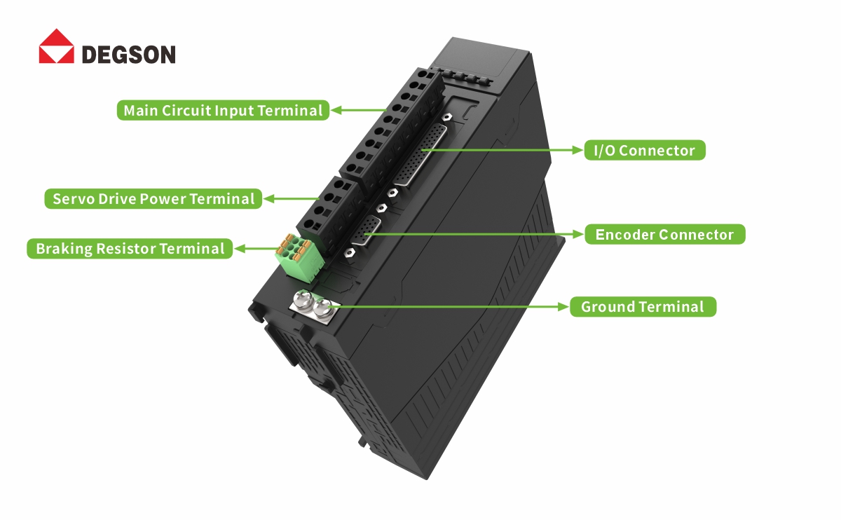
Overview of DEGSON connector families across power, signal, data, and motor-end interfaces
Power transmission — SNAP-LOCK (9EDGKD-HC) pluggable series.
Push-in spring termination with a self-locking buckle, published in two pitches:
| Order code | Pitch | IEC rating | UL rating | Conductor | Strip length |
| 9EDGKD-HC-5.0 | 5.0 mm | 20 A / 500 V (III/3) | 300 V, 20 A (group B), 10 A (group D) | 0.5–2.5 mm² (20–12 AWG) | 10 mm |
| 9EDGKD-HC-7.5 | 7.5 mm | 25 A / 630 V (III/3), 800 V (III/2) | 600 V, 25 A (groups B and C) | 1.0–6.0 mm² (18–10 AWG) | 12 mm |
Both are tested to IEC 61984 / UL 1059 with a PA66 UL 94 V-0 housing and tin-plated copper-alloy contacts, rated −40 °C to 105 °C subject to derating. This series suits pluggable power connections up to 25 A. Where a servo axis draws beyond that range, the pluggable format is no longer the right answer: DG271V-10.0 offers IEC 76 A / 1000 V and UL 300 V / 70 A across 0.2–16 mm² (20–4 AWG) at 10.0 mm pitch to IEC 60947 / UL 1059, but it is a board-mounted push-in spring terminal and is not pluggable—that trade-off between current capacity and field-serviceability should be made deliberately.
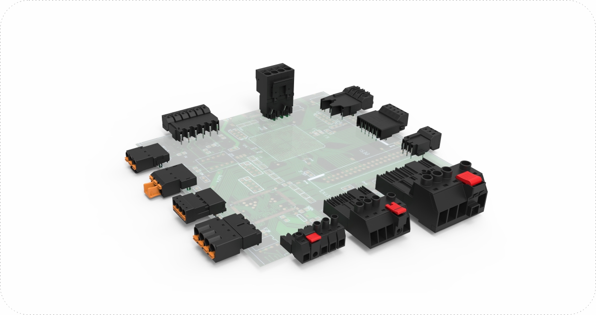
SNAP-LOCK 9EDGKD-HC pluggable terminal block with self-locking buckle
Signal transmission — 15EDGKNH-3.5 and D-SUB.
The 15EDGKNH-3.5 is a 3.5 mm pitch, double-row pluggable PCB connector using push-in spring termination, offered from 4 to 40 poles, rated 9.5 A / 250 V to IEC and 8 A / 300 V to UL, accepting 0.2–1.5 mm² (26–16 AWG), rated −40 °C to 105 °C, with a PA66 UL 94 V-0 housing, tested to IEC 61984 / UL 1059 and carrying UL and VDE marks. Certificate references supplied by DEGSON are UL E228872 and VDE 40045517; both registers are dynamic query databases, so verify them directly through UL Product iQ and the VDE certificate search before publication rather than relying on a quoted number. The D-SUB range offers board-end and cable-end variants with straight and right-angle bodies for integrated wiring in instrumentation.
Verified example — temperature-rise test on 15EDGKNH-3.5.
A 15EDGKNH-3.5-12P plug, mated with its 15EDGRHC-3.5-12P header and tested to IEC 61984:2009, was loaded at 8 A per pole through 0.75 mm² solid conductors in a 40.4 °C ambient. The highest measured conductor temperatures across the sampled poles were 78.3 °C, 90.5 °C, and 89.1 °C, against a 110 °C material limit — a documented pass with test current, conductor size, and ambient all stated (record dated 2018-04-04). Note the scope: the result holds for that pole count, conductor size, and ambient. A higher pole count, a smaller conductor, or a warmer cabinet each require their own derating check, so request the report for the exact order code used in your design rather than applying this figure series-wide.
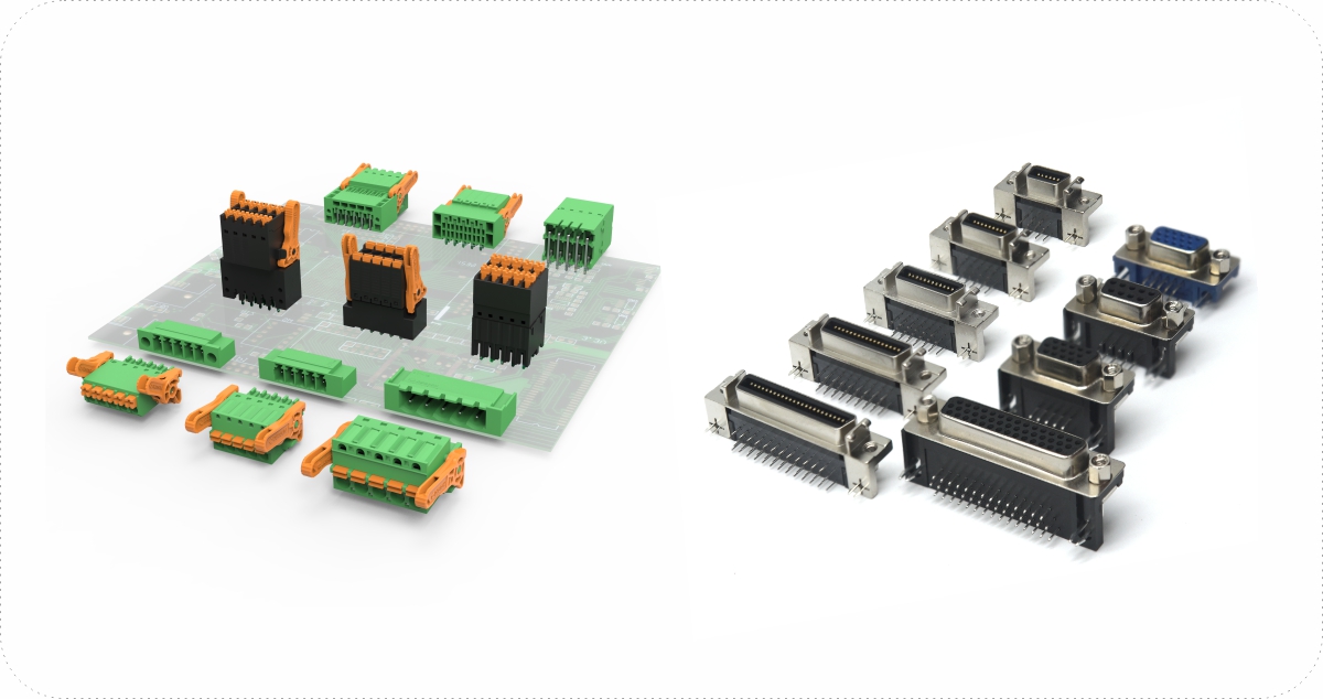
15EDGKNH double-row push-in PCB connector alongside D-SUB variants
Data communication — RJ45 and USB.
The RJ45 range provides latched retention for Ethernet-based servo networks; as noted above, confirm protocol, pin assignment, and cable category against both endpoints rather than treating the connector form as sufficient. The USB range covers test and laboratory data exchange.
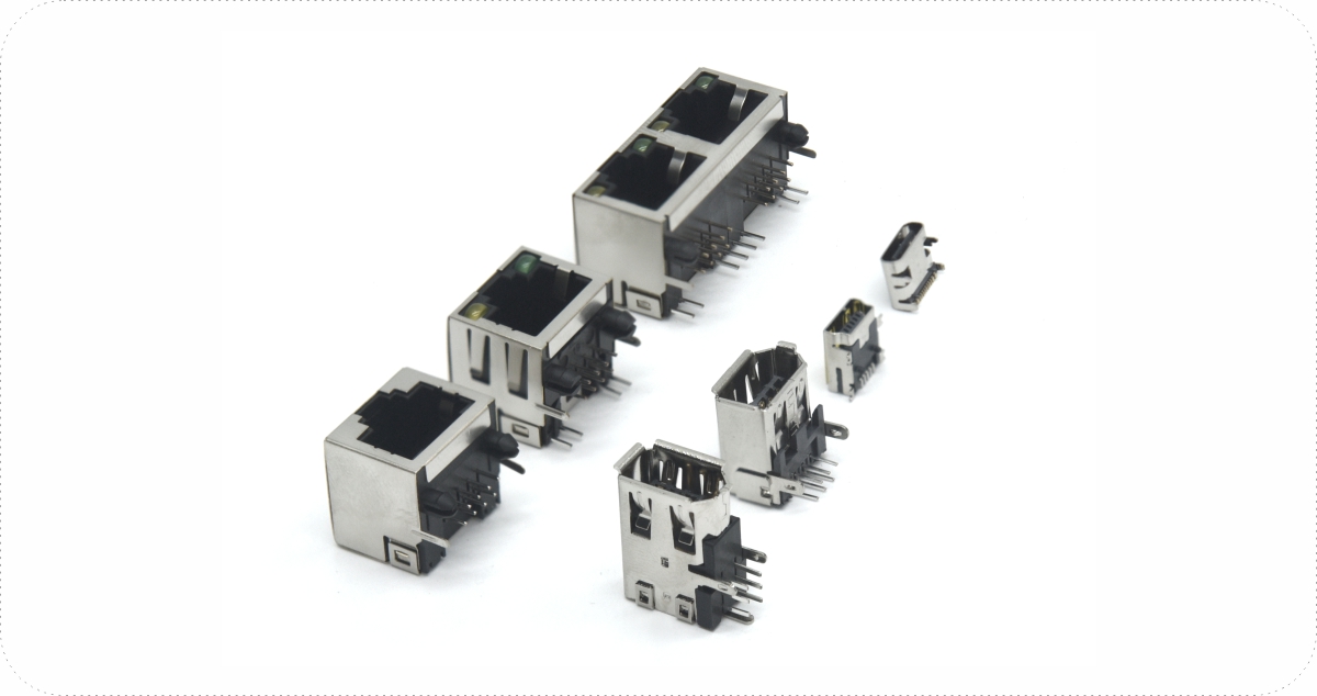
RJ45 industrial Ethernet connector with latching retention
Motor-end — DGFA and M23.
The DGFA servo connector range covers low-power motor-end connections, published as DGFA-S-A (socket), DGFA-S-B (plug) and DGFA variants, in 2-core brake, 4-core power, 2+4 hybrid, and 7/9-core signal configurations for robot end-effectors and assembly equipment. The M23 motor connector range addresses medium-power motors in configurations including 5+PE power, 12/17-pin signal, and 5+3+PE hybrid.
For both ranges, ingress rating, shield construction, and vibration level are specified per order code and are not published on the category pages, so request the data sheet and the IEC 60529 / IEC 60068-2-6 test scope for the exact part before fixing the specification. This is the same boundary described earlier: a motor-end rating is established by the part number and its test conditions, not by the series name.
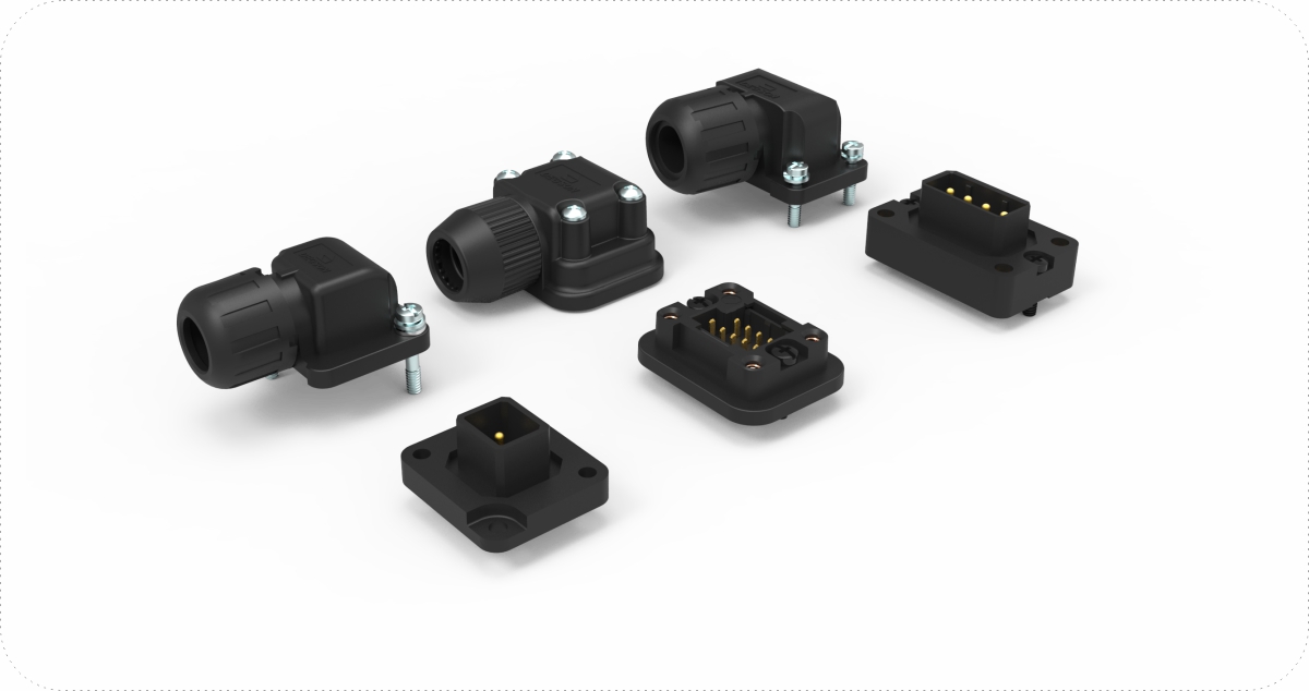
DGFA low-power servo motor-end connector
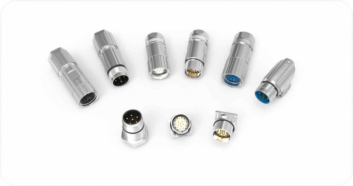
M23 medium-power servo motor connector
To move from shortlist to design-in, browse the corresponding series on the DEGSON website, where each product page carries the data sheet, 3D STP and CAD DXF downloads. For servo projects, request the IEC 61984 / UL 1059 test report and temperature-rise data for your exact order code, and ask for evaluation samples to trial against your own drive, cable, and grounding arrangement before committing the design.
FAQ
Q1: Our encoder feedback is noisy after a cabinet retrofit. Is the connector the likely cause?
Not necessarily, and it is worth checking the bonding before changing parts. Encoder lines carry low-voltage differential signals, so the usual causes are an interrupted shield path, a pigtail bond replacing a circumferential one, or a ground loop introduced by the retrofit. Confirm the screen is bonded at both ends as the drive manual specifies, verify separation from converter output cables, and measure contact resistance before concluding that the connector is at fault.
Q2: Do we need IP67 connectors throughout a servo machine?
Rarely. IP ratings apply to the mated, correctly assembled condition under IEC 60529, and specifying IP67 for connections inside a sealed cabinet adds cost without adding protection. Apply the rating where exposure justifies it—coolant, washdown, dust, or outdoor placement—and confirm the seal material against the actual fluid and cleaning method, since a part that passes a water ingress test may not resist a specific cutting fluid.
References
-
IEC 61984 — Connectors: safety requirements and tests. IEC Webstore
-
UL 1059 — Standard for Terminal Blocks. UL Product iQ
-
IEC 60529 — Degrees of protection provided by enclosures (IP Code). IEC Webstore
-
IEC 60068-2-6 — Environmental testing: vibration (sinusoidal). IEC Webstore
-
DEGSON official product pages: 9EDGKD-HC-5.0, 9EDGKD-HC-7.5, Servo Connector range


