A KNX installation wires devices onto a twisted-pair bus that carries power and data on the same conductors, so the terminal specification follows directly from the cable: KNX TP cable is 2 × 2 × 0.8 mm solid conductor, which is 0.5 mm², and it is colour-coded red/black for the bus pair and yellow/white for the spare pair. A terminal for this bus therefore needs a conductor range covering 0.5–1.0 mm² solid, a matching colour scheme so the bus pair cannot be crossed with the auxiliary pair, and a way to branch one incoming bus line to several devices inside a junction box.
This article covers TP (twisted pair) bus wiring for KNX devices — gateways, actuators and sensors — and the PCB-level terminals inside them. It does not cover KNX IP or KNX RF topologies, where the physical layer is Ethernet or radio and no bus terminal is involved, nor the mains-side wiring of KNX actuators, which follows the installation rules for the load circuit rather than the bus.KNX is one bus defined by several standards, and each one constrains the wiring differentlyKNX (Konnex) is the open international standard for building and home automation buses. It converged three earlier systems — the European Home Systems Protocol (EHS), BatiBUS and the European Installation Bus (EIB / Instabus) — and has been maintained since 1999 by the KNX Association cvba in Belgium, whose membership spans several hundred hardware and software manufacturers.
|
Scope
|
Standard
|
|
International
|
ISO/IEC 14543-3
|
|
European
|
CENELEC EN 50090, CEN EN 13321-1
|
|
United States
|
ANSI/ASHRAE 135
|
|
China
|
GB/T 20965
|
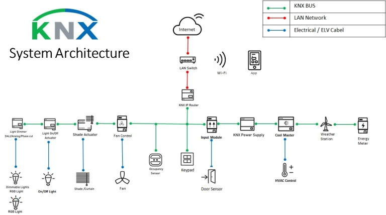
KNX devices divide into four functional roles, and the wiring requirement differs between them. Sensors — temperature, motion, light level — report conditions onto the bus. Actuators — dimmers, relays, valve and blind drives — act on commands, and are the devices that also carry mains-side load wiring. Controllers process sensor data and issue commands. Gateways bridge KNX to BACnet, Modbus or IP, connecting the installation to a building management system.
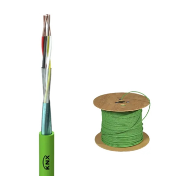
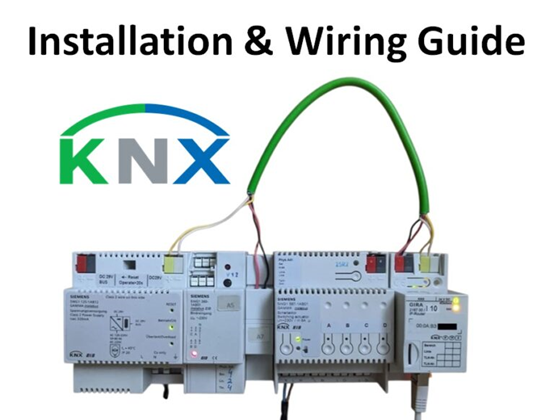
All four attach to the same bus, which is routed in parallel with the power supply rather than daisy-chained through it. That is what makes the branching capability of the bus terminal a design question rather than an installation detail: inside a device or a junction box, one incoming bus pair frequently has to feed several onward connections.The TP cable specification and colour code determine what the terminal must acceptKNX TP1 — the twisted-pair physical layer used in the large majority of installations — runs as a SELV DC bus, nominally 29 V, supplied from a dedicated KNX power supply. Power and data share the same pair, which is why the cable is specified rather than left to the installer.
|
Property
|
KNX TP cable
|
|
Construction
|
2 × 2 × 0.8 mm solid (≈ 0.5 mm² per conductor)
|
|
Insulation colours
|
Red, black, yellow, white (green outer sheath typical)
|
|
Bus pair
|
Red = bus +, black = bus −
|
|
Spare pair
|
Yellow / white, commonly used for auxiliary supply
|
|
Operating temperature
|
−20 °C to +70 °C
|
|
Installation
|
Fixed indoor installation in walls, ducts and ceilings
|
Two things follow from this table, and they are the reason KNX bus terminals look different from general-purpose PCB terminals.
First, the conductor is solid and small. At 0.8 mm diameter the conductor is around 0.5 mm², at the bottom of the range most PCB terminals are built for. A push-in spring terminal handles solid conductors without a ferrule, which suits field wiring — but the clamp has to be designed for that range, and the strip length has to match. Over-stripping on a 6 mm strip length leaves bare copper outside the housing on a bus that is live at 29 V.
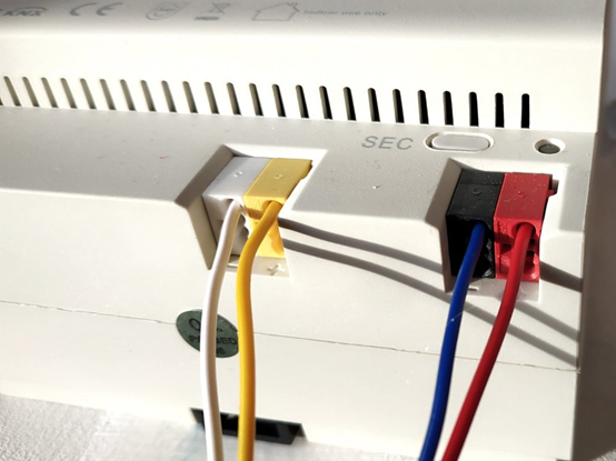
Second, the colour code is functional, not decorative. Because red/black and yellow/white carry different functions, a terminal that repeats the same colour coding on its housing gives the installer a direct visual check. Crossing the bus pair with the auxiliary pair is one of the more common commissioning faults, and it is a fault that colour-matched terminals largely prevent at the point of wiring rather than at the point of testing.
Four criteria select a KNX bus terminalWorking through these in order eliminates most of the catalogue before any datasheet comparison.
-
Conductor range and pitch. The terminal must accept 0.5–1.0 mm² solid, and its pitch has to fit the board layout of a device that is often DIN-rail-mounted and space-constrained. A pitch in the 2 mm class is what makes a multi-pole bus terminal fit inside a compact actuator housing.
-
Colour differentiation. Housing colours matching the cable's function split — one colour pair for the bus supply, another for the auxiliary supply — so that mis-termination is visible before power-up rather than after.
-
Branch capability. Because the KNX bus is routed in parallel, a terminal that internally bridges one input to several outputs removes the external wire nuts or wire-to-wire joints that would otherwise sit in the junction box. A one-in, three-out arrangement covers the common case of feeding three onward devices from a single incoming pair. In the DG220 series this is the four-pole DG220B-2.1-04P-01 paired with the DG220J-01P — one position takes the incoming bus pair and three are bridged out to downstream devices. It is a variant feature rather than a series-wide one: the bridge accessory field on the base two-pole DG220B-2.1-02P datasheet is empty, so specify the four-pole part number if branching is required.
-
Standard and rating basis. This is where specifications most often go wrong. The applicable test specification for the terminal is a component standard — IEC 61984 and UL 1059 for the DEGSON DG220 series, per its datasheet — and it is separate from the KNX device certification discussed in the next section. IEC 60998-2, which covers connecting devices for household installation, is not the standard cited on these datasheets and should not be substituted for them.
KNX certification applies to devices, and a certified component is an input to itThis distinction matters commercially and is easy to overstate, so it is worth setting out precisely.KNX certification is granted by the KNX Association to devices that implement the KNX protocol and pass conformity testing — it verifies interoperability on the bus, not the electrical safety of a component inside the device. A terminal block, by contrast, is certified against component safety standards: UL and VDE approvals for the DG220 series cover construction, materials, creepage and clearance, and temperature rise under UL 1059 and IEC 61984.DEGSON is a member of the KNX Association, and the DG220B has passed KNX certification under two registrations, 854/22666/26 and 854/22667/26. That there are two rather than one is itself the point: the association records certification per product, not per series. Check which registration covers the exact part number you intend to use through the KNX Association rather than relying on a series-level statement.What that does for a device manufacturer is narrower than "reduces certification work", and the accurate statement is this: a component with current UL and VDE approvals lets you reference existing component test data in your own device submission instead of re-testing the terminal, provided the approval covers the exact part number, pole count and material you are using. It does not transfer device-level KNX conformity — that still has to be demonstrated for your product. Certification scope always attaches to specific models and configurations, so verify the certificate for the part number rather than treating the series as uniformly covered.
DEGSON DG220 series ratings and where the series applies
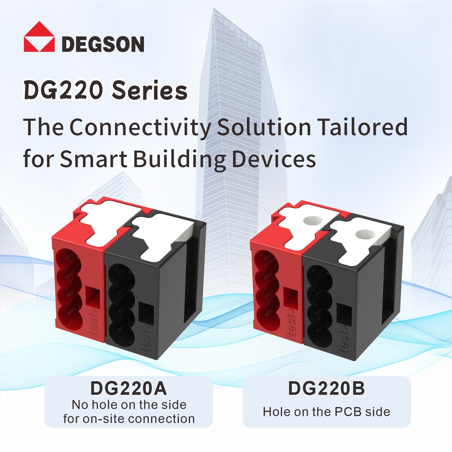
The DG220 series is a PUSH-IN spring PCB terminal built for the KNX bus conductor range, with colour-coded housings — red and black for the bus supply, yellow and white for the auxiliary supply. The verified ratings for the base variant are below; note that the IEC and UL figures describe the same part under two different test regimes.
|
Parameter
|
DG220B-2.1
|
|
Connection method
|
PUSH-IN spring, solid conductor
|
|
Conductor cross-section, solid
|
0.5–1.0 mm²
|
|
AWG range
|
22–18 AWG
|
|
Strip length
|
6 mm
|
|
Pitch
|
2.1 mm
|
|
Rated voltage, IEC (III/2)
|
320 V
|
|
Rated voltage, IEC (III/3 · II/2)
|
250 V · 630 V
|
|
Rated current, IEC
|
6 A
|
|
Rated surge voltage
|
4 kV
|
|
Rated voltage / current, UL (groups B and D)
|
150 V / 7 A
|
|
Contact material
|
Copper alloy, tin-plated
|
|
Insulation material
|
PA66, UL94 V-0
|
|
Ambient temperature
|
−40 °C to +105 °C (per derating curve)
|
|
Test specification
|
IEC 61984 / UL 1059
|
|
Certification
|
UL, VDE; KNX certified (854/22666/26, 854/22667/26)
|
|
Environmental
|
Compliant with REACH / RoHS
|
|
Order number (02P)
|
10060002741
|
Source: DG220B-2.1 product page and datasheet.Three application boundaries are worth stating plainly.The series is specified for solid conductor. At 0.5–1.0 mm² solid it matches KNX TP cable directly. Fine-stranded conductor is outside the published range for this part, so where an installation uses flexible cable on the bus side, confirm the terminal variant before specifying.The DG220J is a needle connector, not a bridge. Pairing DG220B with DG220J produces a wire-to-board connection, extending the terminal to internal device connectivity; the DG220B-2.1-04P-01 with DG220J-01P is the combination that delivers one-in, three-out distribution. The bridge accessory field on the DG220B-2.1-02P datasheet is empty — branching comes from the multi-pole variant, not from a bolt-on bridge.The ratings are bus-level, not load-level. At 6 A IEC and 7 A UL, this series covers the KNX bus and auxiliary supply. It is not intended for the mains-side load wiring of a KNX actuator, which requires a terminal rated for the load circuit and its own overvoltage category.Q1: Can these terminals be used with cable other than KNX TP cable?Within the published conductor range, yes: the terminal accepts 0.5–1.0 mm² solid conductor, equivalent to 22–18 AWG. KNX TP cable at 2 × 2 × 0.8 mm sits inside that range, and its insulation thickness and conductor diameter are matched to the push-in mechanism and the 6 mm strip length. Conductors outside the range are the problem — a thinner conductor may not develop sufficient contact force in the spring, and a thicker one will not enter the clamp. If a project uses non-standard cable on the bus, verify the conductor diameter against the datasheet rather than against the nominal cross-section, since insulation diameter also affects how the conductor seats.Q2: When is internal bridging preferable to joining the bus externally?Internal bridging earns its place where several devices are fed from one incoming pair inside a confined enclosure — a one-in, three-out terminal replaces three external joints, each of which is a potential fault point and each of which consumes space in the box. Where only one onward connection is needed, it saves nothing. The other consideration is serviceability: an internally bridged terminal keeps the distribution point visible and probeable at the terminal, rather than buried in a bundle of wire joints, which shortens fault-finding during commissioning.
-
KNX Association — standard, certification register and membership; DG220B KNX certifications 854/22666/26 and 854/22667/26. knx.org
-
ISO/IEC 14543-3 — Information technology — Home electronic system (HES) architecture. IEC Webstore
-
IEC 61984 — Connectors — Safety requirements and tests. IEC Webstore
-
UL 1059 — Standard for Terminal Blocks. UL Solutions
-
DG220B-2.1 product page and datasheet, order number 10060002741. DEGSON
Specify the bus terminal from the cable, not the other way round: fix the conductor range and strip length from the KNX TP cable, decide whether the enclosure needs internal branching, then check the IEC and UL ratings against the market the device ships into. To evaluate the DG220 series against that sequence, browse the KNX connection products on degson.com, download the datasheet and dimension drawing for the pole count and colour combination you need, and request the UL and VDE certificates plus the KNX certification record covering that specific part number before you commit the board layout.


